LightBox

Back to Portfolio

Problem

To design a lightbox meeting a specified set of user needs in conjunction with the BME Design Fellows Program at the Chesterfield Laboratory at Duke University. Requirements included a sealed enclosure within 4-inch maximum dimensions, an SPST on/off switch, a push button to initiate a 10 Hz 50% duty cycle LED blink for 50 cycles, a 9V battery with reverse polarity protection, battery replaceability under 5 minutes, a single-sided PCB designed and soldered in-house, and survivability of a 3-foot drop, all under a $20 duplication cost and 0.5 lb weight limit.

Outcome

All listed user requirements were met. A full CAD model and mechanical drawings were completed for each enclosure component. PCB layout was designed in KiCad, printed, and hand-soldered. Testing across battery life, battery swap time, duty cycle, blink rate, and cycles on was conducted for 10 trials each with 95% confidence intervals calculated per metric, and all results fell within the specified 5% error margins.

Design

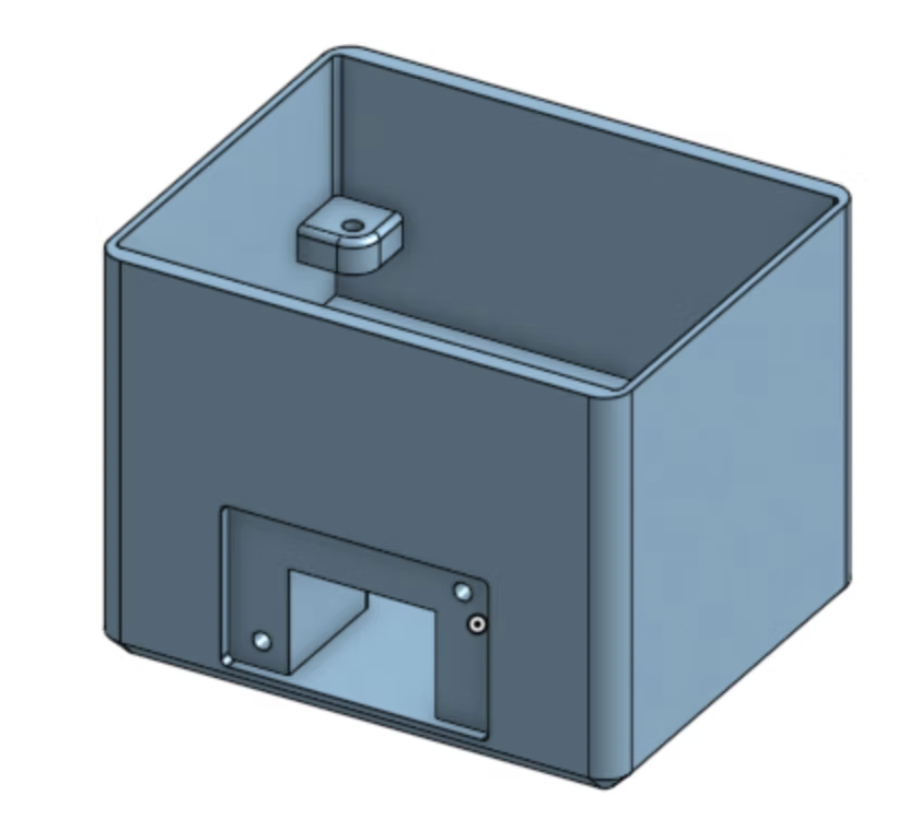
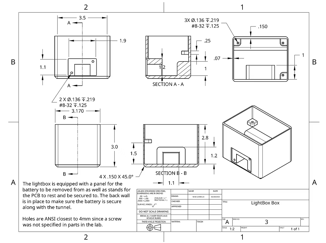
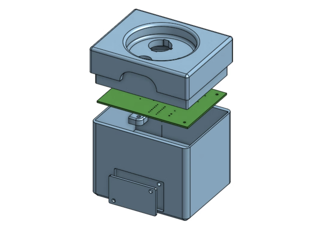
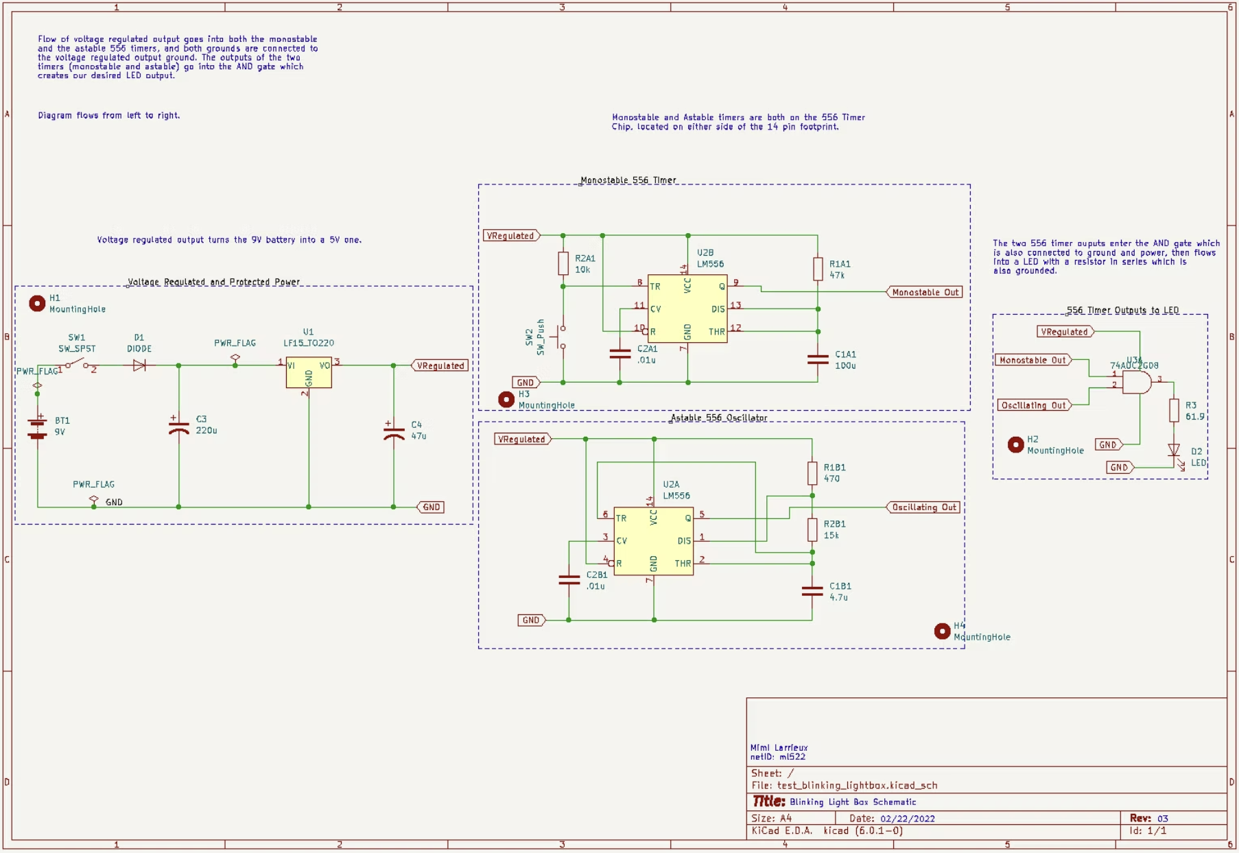
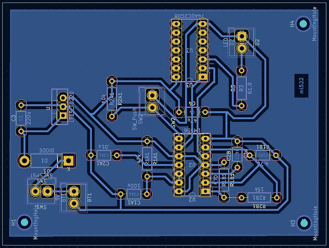
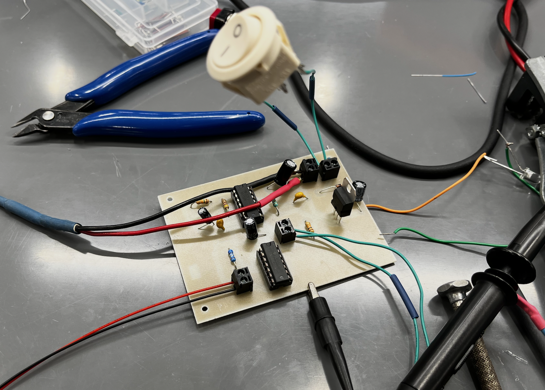
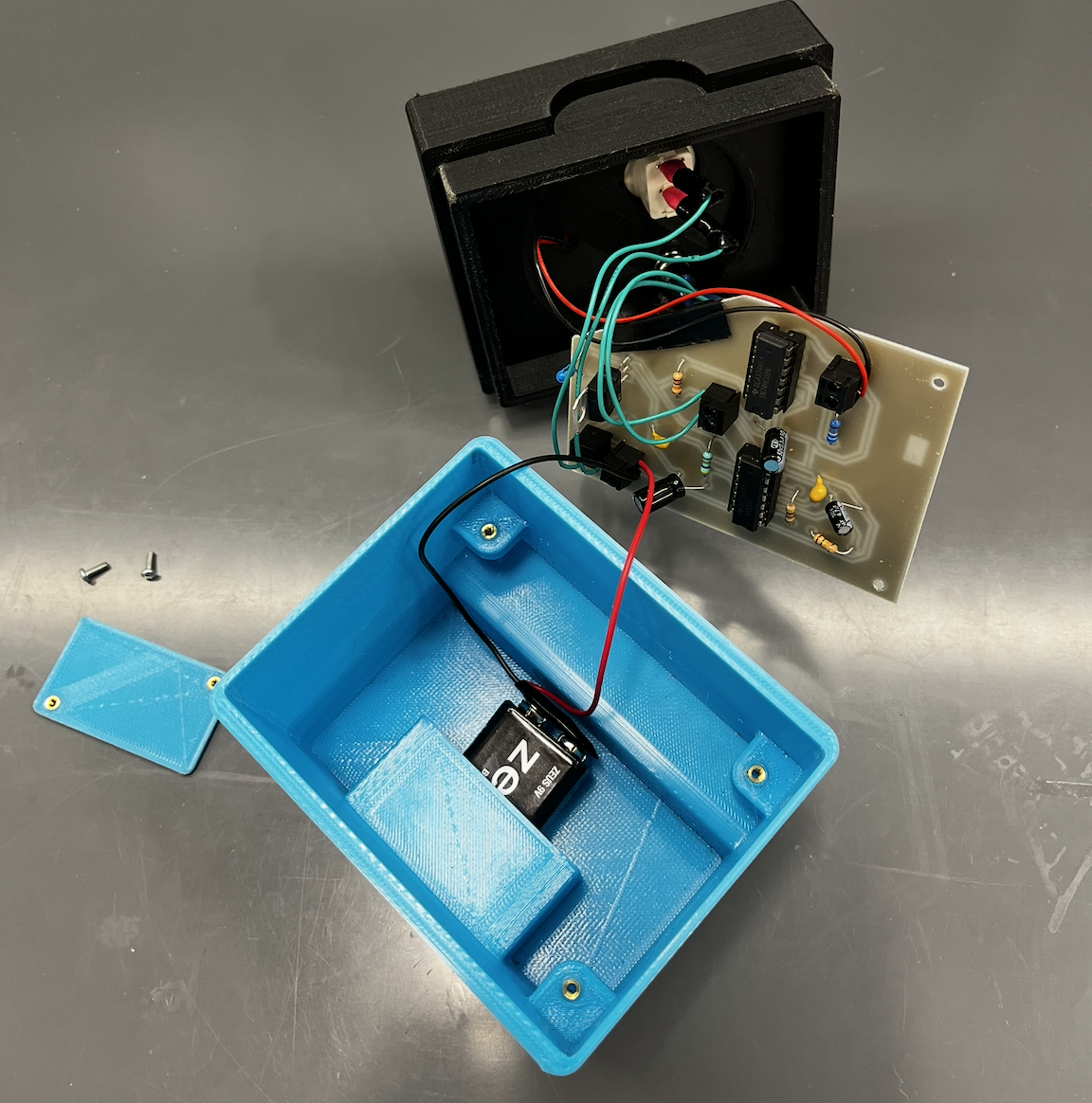
The enclosure consists of a 3D-printed PLA box, a lid with interior lips for secure flush closure, and a front panel, all modeled in CAD with threads added to accommodate component mounting. A mechanical drawings were created for each CAD component. The lid was designed to eliminate any protrusion of elements including the push button, which is secured using a recessed washer. The PCB was designed in KiCad, and the circuit uses a 556 timer IC to drive the LED blink sequence, regulated by a 9V battery with a voltage regulator and reverse polarity protection.

Build

The box was 3D printed, sanded, and assembled. The PCB was designed in KiCad and milled and printed by course instructors. The first version had an oversized layout, incorrect socket footprint labels, and a missing ground fill, requiring a full redesign and re-mill. The second version was more compact and correctly labeled, and functioned as intended after minor corrections including manually bridging a ground trace to the copper fill. Components were soldered onto the board, and the enclosure was printed, sanded, and assembled with all hardware.

Testing and Iterations

Five metrics were tested over 10 cycles each: battery life (95% CI: 14.63 ± 0.188 hrs), battery swap time (59.4 ± 1.82 sec), duty cycle (49.3 ± 0.053%), cycles on (49.99 ± 0.221), and blink rate (9.64 ± 0.007 Hz), all within required margins. Mid-testing, the voltage regulator capacitors were replaced after repeated diode failures, which resolved the issue and enabled stable prolonged operation. The enclosure also went through two lid redesigns, first to improve fit, then to fully recess the push button.

Reflections

The design process involved multiple PCB iterations driven by layout errors and component failures, making it a lesson in catching mistakes early versus patching them downstream. Future iterations would prioritize a more compact PCB and thinner enclosure walls to create more margin within the size and weight constraints, rather than just barely clearing them.